Today I’ll to try to explain how the cast.p8 demo works. The cart uses a kind of “raycasting” to render a first-person view of a simple level. Googling raycasting will give you a heap of fantastic tutorials, but Zep’s implementation is pretty different from what you tend to see.
If you’re gonna read the cast.p8 code concurrently with this post, keep in mind some code won’t match up exactly with Zep’s. I’ll explain the key differences later though.
The Level
So we’ve got a player who moves around a 3D level, which is just a grid of tiles at different heights. It’s represented by a grid of sprites in the map. The height of the tile is given by the value of the sprite. MGET(X,Y) will give us the height of tile at x,y.

The Player
PL is our player object which stores an x,y,z position, and the direction they’re facing PL.D as an angle. Player input is read during the _UPDATE function.
PL={}
PL.X = 12
PL.Y = 12
PL.Z = 12
PL.D = 0.25
Generating the Rays
In raycasting, we send out a ray from the player for each x-coordinate on the screen. We follow the path of the ray until it hits a wall. The distance that the ray travelled gives the height of the wall, which we draw as a vertical line.

At the start of DRAW_3D() we initialize two unit vectors (V.X0,V.Y0) and (V.X1,V.Y1) which are angled slightly left and slightly right of the player direction.
V.X0 = COS(PL.D+0.1)
V.Y0 = SIN(PL.D+0.1)
V.X1 = COS(PL.D-0.1)
V.Y1 = SIN(PL.D-0.1)
These vectors represent the two outer sides of the viewing triangle. 0.1 is a magic number which determines the field of view. As we go from the left side of the screen to the right, we interpolate between these two vectors to find the corresponding ray vector (VX,VY):
FOR SX=0,127 DO
 ...
 LOCAL T=SX/127
 VX = V.X0 * (1-T) + V.X1 * T
 VY = V.Y0 * (1-T) + V.Y1 * T

Edge Finding
Now that we’ve generated rays for each x-coordinate, we have to be able to find which tiles they pass through.
A simple way could be to test points separated by a constant distance along the ray. However this results in accidently skipping over some tiles that should have been checked. We could decrease the distance we move along the ray, but this becomes too inefficient.

Instead we’ll be clever and only check where the ray intersects with edges of tiles!

Here’s how we’ll do it: At any point on the ray, we want to jump to either the next column or the next row. We chose the one that is closest by distance along the ray’s path. We represent the distance to the next column and the next row (along the ray) as DIST_X and DIST_Y.

Let’s start by assuming that the ray originates from an integer position on the grid. What should DIST_X and DIST_Y be initialised to? I’ll refer to these specific initial values as STEP_X and STEP_Y.
For STEP_X, we need to move along one tile in the x-direction by moving STEP_X units in the diagonal. So let’s use a right-angle triangle of width 1 and hypotenuse STEP_X.

Since this is a similar triangle to our ray vector, we can find STEP_X using the ratio STEP_X / 1 = 1 / abs(VX). Doing the same for STEP_Y, we end up with:
SKIP_X = 1/ABS(VX)
SKIP_Y = 1/ABS(VY)
Now what do we do when the ray starts in another position? We need to scale our initial values based on how close the ray starts to the edge it will next hit. Conveniently the scale factor we need is this exact distance, only in the horizontal or vertical direction (e.g. if the ray is 0.8 units away from the right edge, then SKIP_X should be scaled by 0.8).
If the ray is going in the positive x-direction, X%1 will give the horizontal distance from the ray to the closest left edge, so 1-(X%1) will give the distance to the closest right edge. In the negative direction, X%1 is what we want.
IF (SGN(VX) > 0) THEN
 DIST_X = 1-(X%1) ELSE
 DIST_X =   (X%1) END
IF (SGN(VY) > 0) THEN
 DIST_Y = 1-(Y%1) ELSE
 DIST_Y =   (Y%1) END

DIST_X = DIST_X * SKIP_X
DIST_Y = DIST_Y * SKIP_Y
We can finally start moving down the ray! We go into a while loop, and on each iteration we choose between the next column or row. If DIST_X < DIST_Y then go to the next column, otherwise go to the next row.
If DIST_X < DIST_Y, we travel along the ray by distance DIST_X, so we need to decrease DIST_Y by DIST_X, and reset DIST_X to the initial value SKIP_X. We do the same for the vertical case:
SKIP=TRUE
...
WHILE (SKIP) DO
 IF (DIST_X < DIST_Y) THEN
  ...
  DIST_Y = DIST_Y - DIST_X
  DIST_X = SKIP_X
 ELSE
  ...
  DIST_X = DIST_X - DIST_Y
  DIST_Y = SKIP_Y
 END
END
Rad! Now we also need to keep track of where we are along the ray. Before the loop let’s initialise some variables that we’ll use: TDIST=0 to keep track of the total distance travelled along the ray, as well as IX=FLR(PL.X) and IY=FLR(PL.Y) to keep track of which cell we’re in. It also turns out to be useful to know if we’re checking a row or a column, so we’ll mark that with LAST_DIR.
Within the loop, we increase TDIST by the distance we travel, and increment IX and IY according to the direction the ray is going:
WHILE (SKIP) DO
 IF (DIST_X < DIST_Y) THEN
  ...
  TDIST = TDIST + DIST_X
  IX=IX+SGN(VX)  --SGN(VX) RETURNS -1 OR 1 DEPENDING ON THE SIGN OF VX
  LAST_DIR = 0
 ELSE
  ...
  TDIST = TDIST + DIST_Y
  IY=IY+SGN(VY)
  LAST_DIR = 1
 END
END
Our program now goes along every ray, correctly finding every grid intersection. Great, now it’s time to use this stuff to draw some lines!
A Classic Raycaster
Before we finish off the code it’ll be useful to look at a simple raycaster, which uses 2D levels like in Wolfenstein 3D. What does the rendering code look like in this case?

Once a ray hits a wall, we want to find the position of the foot of the wall on the screen. We can do this with SH/2 + K/TDIST, where SH is the screen height, and K is some constant. Intuitively, as TDIST gets bigger (further away), the foot of the wall shrinks toward the horizon. Similarly the position of the top of the wall is SH/2 - K/TDIST.
Since close walls obscure further walls, we only need to draw one line per ray. In PICO-8 the end result could look something like this:
WHILE SKIP DO
 ...
 LOCAL COL = MGET(IX,IY)
 IF COL > 0 THEN
  LOCAL H=50/TDIST
  LINE(SX,64-H,SX,64+H)
  SKIP = FALSE
 END
END
Drawing the Tiles and the Walls
Now what do we do with our 3D level? Imagine a staircase that ascends in front of the player, we’ll need to draw all the different floor heights and numerous walls, spooky!
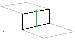
Let’s start by working out how to draw the ground of a tile. Note that the ground is just the space between the edges of the tile. We can think of these edges as the feet of some imaginary walls surrounding the tile. This is great since we know about walls from the 2D raytracer! So when a ray passes through a tile, we find where on the screen the feet of walls would be for the two points that the ray intersects. Then we just draw a vertical line between them!

Now that we can draw the tops of tiles, we’re going to use them to draw walls too (our 2D method won’t help us much anymore). Walls are just the space separating the edges of two tiles, so we just draw a vertical line between points calculated for the two tiles' edges.
So now we just need to implement a way to find the height of edges for different tiles.
To do this we just make a small change to the code from earlier: we scale render height K based on the tile’s height relative to the player. Tiles higher above the player should be scaled more. Tiles at the same height as the player’s head should be drawn at the horizon. So hopefully you can see that TILE_HEIGHT-PLAYER_HEIGHT is what we want:
TILEH = MGET(IX,IY)
Z = PL.Z+5
EDGE_Y = SH/2 - K*(TILEH-Z)/TDIST
Notice that we use PL.Z+5 for the ray height, which simulates our character having a torso.
Putting it All Together
As we travel down a ray, we’ll draw the floor and walls of every tile we see, gradually filling the column of pixels from bottom to top. We’ll keep track of how far we’ve draw with SY, which is initialised to 127.
We should try to draw the ground for every tile on the ray, but only where we haven’t drawn on the screen yet (above SY). Similarly we’ll only draw walls when the ray moves to a higher tile, and only draw the section that is visible.
Let’s imagine how this could work out. For the first edge a ray finds, we’ll want to draw some ground from the bottom of the screen (SY=127) up to that edge. If you think about it this is the ground of the tile that the ray started in, not the tile that IX and IY point to currently! We still need the current tile though: if it happens that the previous is lower than the current, then we need to draw a wall between the edges of the two tiles.
Extrapolating this out, every iteration we need the position of two edges (EDGE1 and EDGE2), one on the previous tile and the other on the current. We'll use these to draw floor from SY to EDGE1, and a wall from EDGE1 to EDGE2. Hence we need to keep track of the height of the previous and current tile. We don’t need the previous TDIST, since both edges are located TDIST along the ray.

We’ll keep track of the previous tile with COL0 and the current tile with COL, updating them on every iteration with:
COL0=COL
COL=MGET(IX,IY)
For this to work on the first iteration we’ll need to initialise COL to MGET(IX,IY) before the loop begins.
Now let's use these two values to find the screen position of the two edges. Remember that the first edge EDGE1 is associated with the previous tile COL0, and the second EDGE2 is associated with the current tile COL, but both are TDIST along the ray.

LOCAL K=12.8
LOCAL Z=PL.Z + 5
EDGE1 = 64 - K*(COL0-Z)/TDIST
EDGE2 = 64 - K*(COL-Z)/TDIST
We’re almost done! The last thing to take care of is making sure to break out of the loop. All we need to do is stop once we reach the outer walls, which have a special height of 15:
IF (COL==15) SKIP=FALSE
Our Baby is Ready
We can finally finish the WHILE SKIP DO loop! Here it is as a big chunk for you to mull over:
WHILE (SKIP) DO
 IF (DIST_X < DIST_Y) THEN
  ...
 ELSE
  ...
 END

 --PREV AND CURRENT TILE PROPERTIES
 COL0=COL
 COL=MGET(IX,IY)

 --RAY HIT AN OUTER WALL
 IF (COL==15) SKIP=FALSE

 -- FIND SCREEN POSITIONS OF EDGES
 LOCAL K=12.8
 LOCAL Z=PL.Z + 5
 EDGE1 = 64 - K*(COL0-Z)/TDIST
 EDGE2 = 64 - K*(COL-Z)/TDIST

 --DRAW FLOOR FROM SY TO EDGE1 (IF EDGE1 IS ABOVE SY)
 IF EDGE1 < SY THEN
  COLOR(11)
  LINE(SX,SY,SX,EDGE1)
  SY = EDGE1
 END

 --IF CURRENT EDGE IS HIGHER THAN THE PREVIOUS
 --DRAW WALL FROM SY TO EDGE2
 IF COL > COL0 THEN
  IF EDGE2 < SY THEN
   COLOR(7)
   LINE(SX,SY,SX,EDGE2)
   SY=EDGE2
  END
 END
END
If we implement _DRAW() then we can give this baby a spin:
FUNCTION _DRAW()
 RECTFILL(0,0,127,127,12) --THE BIG BLUE SKY
 DRAW_3D()
END
Here’s what it looks like!

Beautiful. Let’s add some final finishing touches.
First we’ll draw walls facing north or south as white (7) and walls facing east or west as gray (6). Remember LAST_DIR from before? (0 if edge is on east/west side, 1 if north/south side.) Let’s use that guy:
COLOR(6 + LAST_DIR) --TRICKY!
LINE(SX,SY,SX,EDGE2)
Next we’ll draw the lowest tiles as dark green (3) instead of green (11):
COLOR(11)
IF (COL0 == 0) COLOR(3)
LINE(SX,SY,SX,EDGE1)
Lastly, we need to put in a little something to stop a weird glitch from happening. If the player is super close to an edge then EDGE1 just blows up since TDIST is so small, giving an unpleasant visual effect. We can fix this by wrapping the drawing block from the start of this section with IF TDIST > 0.1 THEN ....

That’s it, we’re done! If you just wanted to learn how make something like cast.p8, then you’re good to stop reading now! However if you want to fully understand Zep’s code then you’ll need to read one last section.
Zepludian Geometry
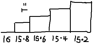
There is one key detail in Zep’s code that I conveniently haven’t explained: Zep chose to represent player and tile height very unconventionally. Rather than height being 0 for the floor and increasing by one for each tile height (as we’ve assumed in this tutorial), tile heights actually start at 16 and decrease by 0.2 for each tile. In other words, if you expected heights to be stored as Z they are actually stored as 16-0.2*Z.
The Zepludian heights of tiles are represented by CELZ=16-COL*0.2 and CELZ0, which are used in place of COL and COL0. The main effect of this swap is that signs and comparisons on these values are often reversed to compensate. For example EDGE1 = 64 - K*(COL0-Z)/TDIST becomes SY1 = 64 + K*(CELZ0-Z)/TDIST, and IF COL > COL0 becomes IF (CELZ < CELZ0). Additionally Zep’s K value is 5 times bigger (from 12.8 to 64) since the heights are now 0.2 units apart.
Lastly Zep expanded the calculation SY1 = 64 + 64*(CELZ0-Z)/TDIST across multiple lines, which might confuse you at first:
SY1 = CELZ0-Z
SY1 = (SY1 * 64)/TDIST
SY1 = SY1 + 64
Bye!
With that explained, I think we’ve covered everything! Hope you enjoyed this read. Feel free to contact me if you have any suggestions or corrections.
Credits and Further Reading
- First raycasting diagram by Hunter Loftis, from his raycasting tutorial “A first-person engine in 265 lines”
- Lode’s Raycasting Tutorial
No comments:
Post a Comment